Torsional rigidity test jig
Texas A&M Formula SAE EV, chassis subteam · AME26 chassis
As an apprentice on the Texas A&M Formula SAE EV chassis subteam, I designed a test jig that measures how stiff the AME26 chassis is in torsion, so the team can check its FEA against the real frame. The back of the chassis is anchored into concrete. The front sits on a center pivot with long lever arms, so a weight hung on one side twists the chassis with a known torque. I designed it from scratch in SolidWorks, and it’s about to be manufactured.
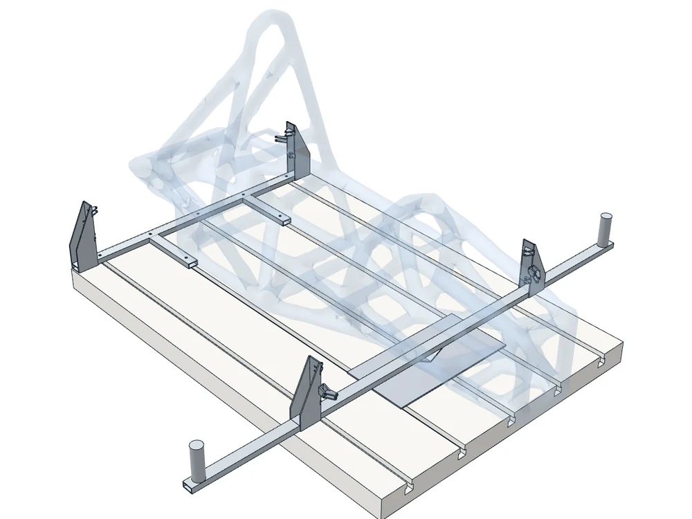
Drag to rotate. Click a part, or turn on Labels, to see what it does. The see-through frame is a deliberately rough outline of the AME26 chassis, there to show where the car sits. The car’s suspension and other team parts aren’t shown.
Why test it
Torsional stiffness is how much torque it takes to twist one end of the chassis by one degree relative to the other. It’s one of the main numbers a Formula SAE chassis is designed around, and it’s usually predicted with FEA.
An FEA result is only as good as its model: how the joints are represented, the tube properties, and above all the boundary conditions. Twisting the real frame by a known amount is the way to find out whether the model can be trusted.
How the jig works
- The rear is held fixed. A welded steel fixture is anchored into concrete. Its mock uprights, made from water-jetted and welded steel, stand where the rear wheel uprights would be, and the suspension is replaced with rigid parts so the back of the chassis can’t move.
- The front can only roll. The front beam rests on a V-shaped pivot at the car’s centerline. Mock uprights on the beam hold the front of the chassis the same way the rear ones do.
- Weights apply a known torque. The beam extends past the mock uprights to a post at each end, 1.15 m from the pivot. A weight hung on one post twists the front of the chassis about the pivot with a torque of weight × lever arm.
- Twist gives the stiffness. Comparing the applied torque with how far the front rotates relative to the fixed rear gives the torsional stiffness, K = T / θ, which can be compared directly with the FEA prediction.
Components
| # | Component | What it does | 3D model |
|---|---|---|---|
| 1 | Rear fixture, welded steel | Anchored into concrete. Holds the back of the chassis still, with triangular mock uprights where the rear wheel uprights would be. | |
| 2 | Rear suspension mounts | Water-jetted face plates and clevis tabs on the mock uprights, where the suspension links connect | |
| 3 | Front lever beam, welded steel | Rests on a V-shaped center pivot, with weight posts 1.15 m out on each side | |
| 4 | Front suspension mounts | The same face plates and clevis tabs, on the mock uprights of the lever beam | |
| 5 | Pivot plate | The plate the V-shaped pivot sits on |
Status and next steps
We were assigned the jig in mid-September. The design is finished and it’s about to be manufactured. Once it’s built, the chassis goes on the jig and the measured stiffness gets compared with the FEA prediction. I’ll add the results here when we have them.
This was also my first project in SolidWorks. Before this, I’d used Onshape and Fusion 360.
 Next projectBrake pedal assembly