Brake pedal assembly
Texas A&M Formula SAE EV, chassis subteam design challenge
As part of applying to the Texas A&M Formula SAE EV chassis subteam, I designed a complete brake pedal assembly. It uses a machined steel pedal on a floor pivot, a balance bar that slides in a slot in the pedal to drive twin master cylinders, a mechanical over-travel stop, a brake over-travel switch (BOTS), and a line-pressure sensor for the brake system plausibility device (BSPD).
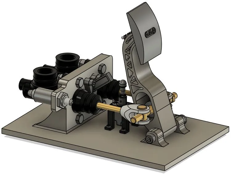
Drag to rotate. Click a part, or turn on Labels, to see what it does. Press Play, or pick a numbered position, to move the pedal the way it moves in the CAD model.
What the pedal has to do
A brake pedal has two separate requirements that are easy to mix up:
- Structural: the pedal and its mounts must survive a 2,000 N force on the pad without failing. That’s the Formula SAE rules load, far more than a driver normally applies.
- Functional: a driver must be able to lock the brakes with a comfortable leg force, within a pedal stroke that feels firm and consistent.
On top of that, an EV has safety and sensing requirements that tie the pedal into the car’s electronics:
- Two independent hydraulic circuits (front and rear), so one failure can’t take out all braking
- A brake over-travel switch (BOTS) that opens the shutdown circuit if the pedal travels too far, which would mean a hydraulic failure
- Brake pressure sensing for the BSPD, which cuts motor power if the driver brakes hard while the car is still under power
Components
| # | Component | Why it’s there | 3D model |
|---|---|---|---|
| 1 | Machined pedal arm, 4130 steel | Floor pivot in double shear. A slot near the pivot drives the master cylinders at a ~6:1 pedal ratio. | |
| 2 | Bolted toe pad | A separate part, so it can be replaced as it wears or moved for driver fit without remaking the pedal | |
| 3 | Balance bar (Tilton 600-Series) | Splits force between front and rear circuits. Its spherical bearing rides in the pedal slot. | |
| 4 | Twin master cylinders (Tilton 75-Series) | One for the front brakes and one for the rear, giving two independent circuits | |
| 5 | Mechanical over-travel stop, 4130 steel | A hard stop that takes the load into the base plate so the master cylinders are never overloaded | |
| 6 | BOTS switch (Honeywell 2T1-6) | A mechanical double-pole toggle switch tripped directly by the pedal arm | |
| 7 | Line-pressure sensor (Texense FPS-V2) | Measures brake pressure for the BSPD |
The slot linkage. Instead of a fixed clevis pin, the balance bar’s spherical bearing rides along a slot machined into the pedal near the pivot. Placing the bar close to the pivot sets the ~6:1 ratio. The slot’s length is sized so that the pedal’s full swing translates into the master cylinders’ 1.1 in of travel.
The pedal arm. The lightening pockets follow the bending moment. The moment is highest at the slot and falls off toward the pad, so the arm keeps the most material where the load is highest and sheds it where it isn’t needed.
Four pedal positions
I laid out the pedal’s travel so each safety feature engages in the right order:
| Position | What happens | 3D model |
|---|---|---|
| 1 · Rest | The pedal rests at 76.8° | |
| 2 · Lock-up | About 15° of travel from rest, where the calculated line pressure locks the brakes | |
| 3 · BOTS trip | Past normal braking. The pedal arm trips the BOTS and opens the shutdown circuit. | |
| 4 · Hard stop | The pedal hits the mechanical stop, which takes 2,000+ N into the base plate so the load never reaches the master cylinders |
Checking the failure case: if one hydraulic circuit fails, the pedal travels past lock-up. That single-cylinder failure reaches 3° past the BOTS trip point before the hard stop, which confirms the switch catches the failure it exists for.
Shutdown & sensing
- The BOTS reads pedal angle directly. It’s tripped by the pedal arm itself, not by anything downstream. If the balance bar or a pushrod fails, the pedal still swings far enough to trip it. It’s a mechanical double-pole switch with a manual reset, placed out of the driver’s reach from the seat.
- The pressure sensor feeds the BSPD. It’s plumbed into the front of the mounting plate. Its trip threshold is set below lock-up pressure and at or under 30 bar, so a hard stop registers before the wheels lock.
FEA at 2,000 N
I ran static stress analysis in Fusion 360 with the 2,000 N rules load on the pad. Most of the work went into getting the boundary conditions right, because they decide whether the peak stress is real or an artifact of how the model is held.
- First model: the pivot and slot were fixed rigidly. The peak landed right at the pivot, but rigid constraints make a joint stiffer than it really is, so that peak was partly caused by the constraint.
- Improved model: I added the balance bar so it reacts the load through the slot, like the real linkage. The peak stress dropped about 6% and moved off the pivot to where the bending-moment diagram predicts it should be.
- Second load case: the pedal pushed against the over-travel stop. Both load cases peak within a few percent of each other, so no single case dominates and the part is reasonably balanced.
- Mesh convergence: I used adaptive mesh refinement until the peak stress changed less than 5% between steps. The original case flattened to a 0.4% change on its last step.
This was my first FEA project, so these results have limits. What I’d do with more time covers the analysis I didn’t finish.
What I’d do with more time
This challenge was my first time using FEA, and it had a firm deadline. Most of that time went into learning to set up a trustworthy model: choosing boundary conditions, understanding why a rigid constraint creates a false stress peak, and learning what mesh convergence actually shows. That meant some work I planned didn’t get finished. I’d rather say so here than hide it.
1 · The FEA isn’t fully converged
The original load case converged cleanly: its last mesh refinement changed the peak by only 0.4%. After I improved the boundary conditions, the updated case passed the 5% convergence target, but its stress was still rising with each refinement. It hadn’t leveled off. Given more time, I would:
- tighten the convergence target to 1–2%, refining the mesh locally around the stress peak so the run stays fast
- re-plot the mounting plate and stop on their own color scale, so their stresses aren’t hidden by the pedal’s much higher peak
- check the reaction force at the balance bar against 2,000 N × pedal ratio, and use it for a hand calculation of bearing stress at the slot
- state the contact assumptions explicitly: bonded vs. sliding contact at the bearing, and how the bar ends are constrained
2 · The slot linkage can side-load the master cylinders
I chose the slot to turn the pedal’s rotation into straight-line master cylinder travel with a compact, high-ratio linkage. The catch is that the slot swings through an arc as the pedal rotates. Even though the bearing slides along the slot, the force it pushes with isn’t perfectly in line with the master cylinder pushrods. That off-axis part is a side load, which can bend the pushrods and wear the master cylinder seals. Master cylinders are built for straight-in axial load.
I’d address it by trying, in rough order:
- Quantifying it first: the angle between the slot force and the pushrod axis at each pedal position, and the resulting side load at 2,000 N
- Adding pushrods with rod ends at both ends, so they can angle freely and carry only axial load. This is the standard approach.
- Trunnion-mounting the master cylinders so they pivot to follow the linkage
- Reshaping the slot so the bearing stays closer to the pushrod axis through the working range of travel
Knowing where a design is weak is part of the design. These are the first things I’d fix in a second revision, and the first questions I’d want to discuss with the chassis team.
 Next projectScorpius: vision-guided flywheel launcher robot